Lithium Battery

Building a Bridge

This has nothing to do with Karma or friendships or anything like that. This is about building a battery!

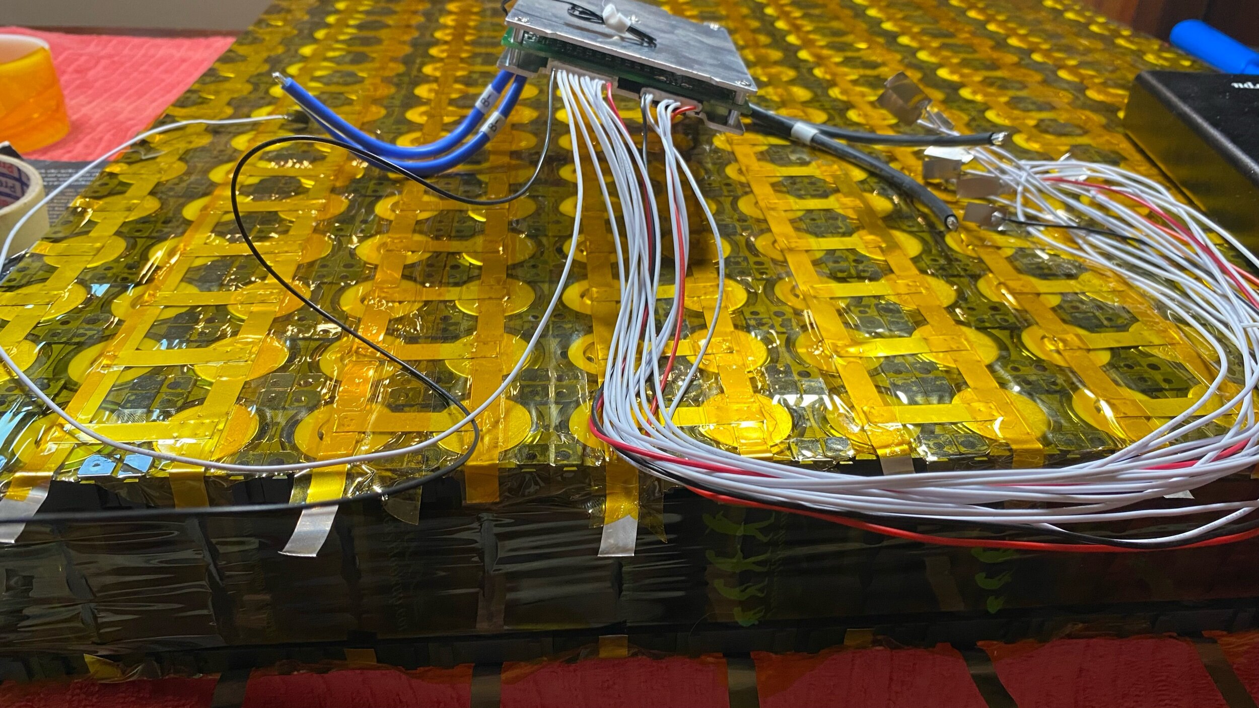
In the battery being built above, the cells are not aligned in neat and even patterns. This is due to space limitations and just makes things complicated. With a little thought, major problems can be avoided, and the implementation takes a small amount of effort.

In this example, I’m building a 16s16p battery. That’s fancy talk for a 48v battery made up of a ton of tiny battery cells. Each cell is 3.2v, and when I link 16 of them up in series, I end up with 51.2v (which ironically is considered a 48v battery). Each cell is only 6ah, so if I just linked 16 of them up in series I would have a 48v battery that holds 6amps; not very useful to power the electric motor in our sailboat along with all of our house loads. To beef up the amp capacity a bit, we simply add more cells in parallel, 15 more to be precise! This gives us a battery that will hold 16x6=96 amp hours and is made up of 16 cell groups in series.

The final result is 16 series and 16 parallel, or also called a 16s16p battery.

That’s cool and all, but why do the cells need to be in strange interlocking patterns? Space. Being how these are batteries for a boat, space is never existent and we will need to cram these batteries into wherever we can fit them. We didn’t have the space to fit 16 cells in a row, so we arranged them into an arrangement that is 10 cells wide. This means that each parallel group is 10 cells in a row with another 6 cells crammed around next to them in the next row. The next row can fit 4 more cells of the next group, the following row is 10 of the same, and then 2 more cells spilling over into the next row. This pattern will continue all the way down the line until you finally get to the last cell group where the pattern just ends.

Why does this matter?

You need to know how much power you plan on pulling from your battery at any point in time and then build the battery to handle this load. In our case, the battery will need to supply 400 amps to power our electric motor when it runs at full speed. Building one battery that can yield 400 amps is pretty ridiculous so we did the logical thing of building 5 batteries that combined will yield 400 amps. Each battery only needs to do 1/5th of the work and therefore each battery will only need to yield 80 amps.

80 amps is our magical number and those pretty Ni strips we have linking the cells together can only flow 5 amps.

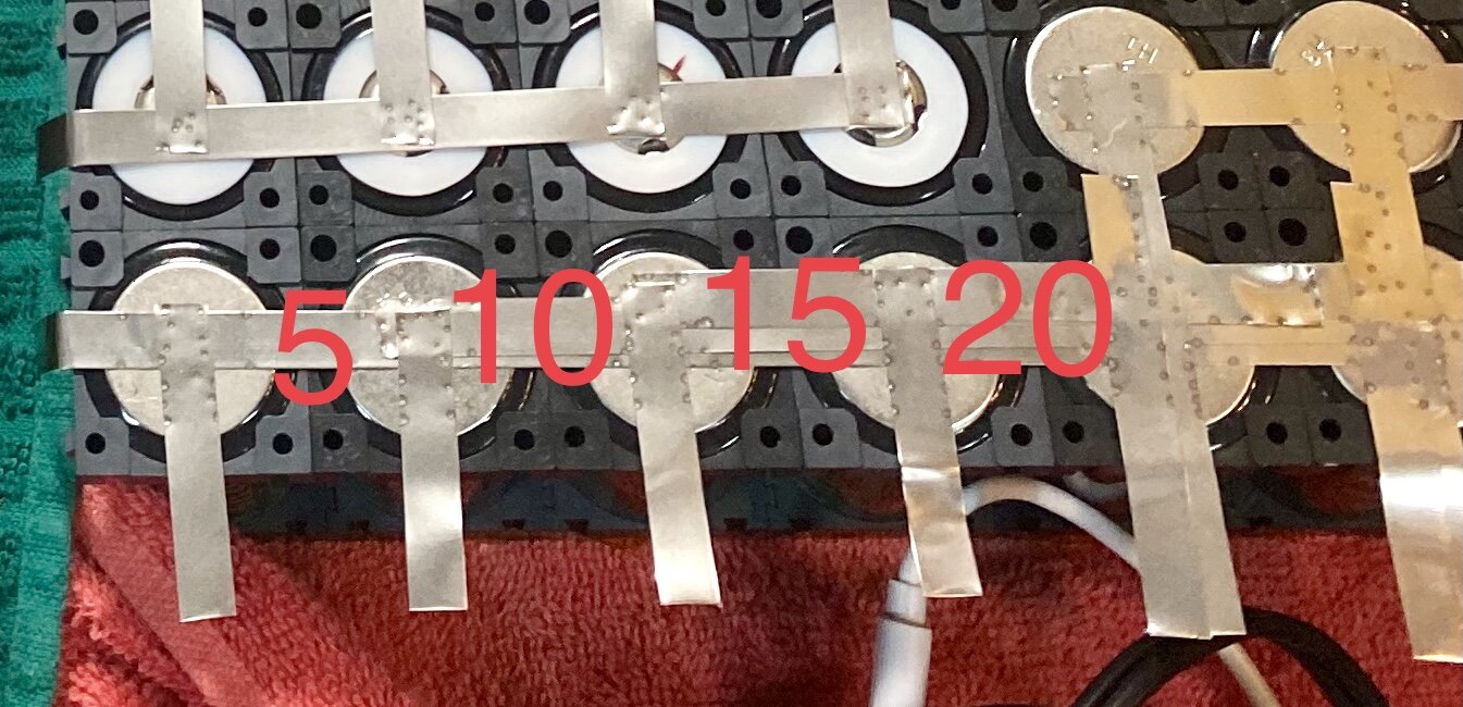
These 4 cells here at the end can become quite the problem! 4 cells can theoretically flow out 4/10ths of the power from the battery. That’s 32 amps that will come rushing out of those cells at full speed from the motor. If we simply connected the cells together with those strips of Ni, power would flow through the area and it would look like everything is fine.

Then when we give the engine a good bit of throttle to move us in a hurry, our battery would break! The little Ni strip that connects those last 4 cells to the rest of the battery can only flow 5 amps. When you start pushing 32 amps through it, that Ni strip will heat up and magically transform itself from a conductor into a fuse. When it gets hot enough, hopefully it will melt and sever the connection. If it remains connected and heated, it can cause the Li cells it is running over to ignite into a flame which will burn with all the fury of Hell, even submerged underwater!

The solution is very simple: Build a bridge.

The last cell will flow out the least amount of power, but the cell leading to it will flow the amount of power that it needs plus the amount of power of the cell downstream from it. The next cell over will have the same conundrum.

By stacking the Ni strips, the amp capacity of the connections increases by 5 amps at each stack. This stacking is called a “bridge” as it bridges a pass that would otherwise serve as an electrical bottleneck. This bridge stacks up to look like the silhouette of an arch bridge which will then flow the power across the gap.

It is important to remember that the bridge needs to extend out the other side in the same manner, otherwise the bottleneck simply gets transferred.

If you notice, I didn’t build the bridge up to 35 amps, but instead stopped at 20. This is because the 80 amps that will flow out of the side of the battery are being directed out through the strips that run off to the sides.

Since we need to flow 80 amps and each strip carries 5 amps, we would need 16 strips to be safe. By doubling the strips, we create a flow of 10 amps out certain cells while single strips only flow 5 amps. This area beyond the bridge only has single strips, meaning that only 20 amps will leave the battery in this area and therefore 20 amps needs to flow by the bridge.

When you build your battery, trace out how the electrons will flow along and trace out their path from the positive pole to the negative pole. If you find an area where a bottleneck exists, simply add more strips to increase the ampacity of that portion. When you build a bridge, also look at the areas that feed the bridge and extend the additional strips into those areas as well to account for the added flow of electrons in these narrow areas.

How do you connect a BMS?

You are saving money by building your own Lithium battery bank, excellent! We built a massive 19.2kW` battery bank for $5,000 which would have cost us $18,000 if we bought Battle Born Batteries!

Battle Born Batteries, the gold standard for marine lithium batteries cost around $950 for a 12 volt 100 amp hour battery. This battery will provide 1,200 Watts of power to your application at a price tag of $950, or $1.26 per Watt.

The battery bank we built consists of five 48 volt 96 amp hour batteries, providing us a grand total of 23,040 Watts of power. Each battery contains 4,608 Watts and cost approximately $1000 to make, but contains 4x the power of a Battle Born; and for roughly the same price!

A 48v battery is created by linking 4 12v batteries in series, meaning that each 100ah 48v Battle Born setup would cost a grand total of $3,800!

Needless to say, it’s significantly cheaper to build your own battery than to buy one that is ready made.

Wonderful! You assemble all the cells and the battery is done being built. Then you open up the BMS (Battery Management System) and pull it out of the package. Suddenly the easy assembly turns into a spider web of wires that need to go somewhere and if you get it wrong the BMS will fry! What do you do?!

It’s not really that complicated. The BMS has a lead that runs to each positive cell of the battery and an extra wire (the black one) that leads to the Negative terminal of the battery.

Ok, but what if you are building a high voltage battery with a ton of leads, now you have two black wires! Which one is the negative wire?

Easy, all BMS start with the large plug that has a bunch of wires where the black one on the far left is the Negative and the red one on the right is the positive, unless the BMS needs a supplemental plug to fit all the battery balancing leads, in which case, the smaller plug will be the supplemental and therefore the black wire will be a regular lead instead of the negative.

The Negative wire I have been referring to is called the “Most Negative” wire. The last positive balance lead, which is red on the opposite side of the plugs is called the “Most Positive” wire. With that knowledge alone, you can look at any BMS with any plug configuration and sort out which wire is the most negative, and by default, which wire is the most positive.

The concept is simple: The black wire attaches to the Most Negative terminal, and each wire that follows in sequential order attaches to the next positive cell.

IMG_5604.jpeg

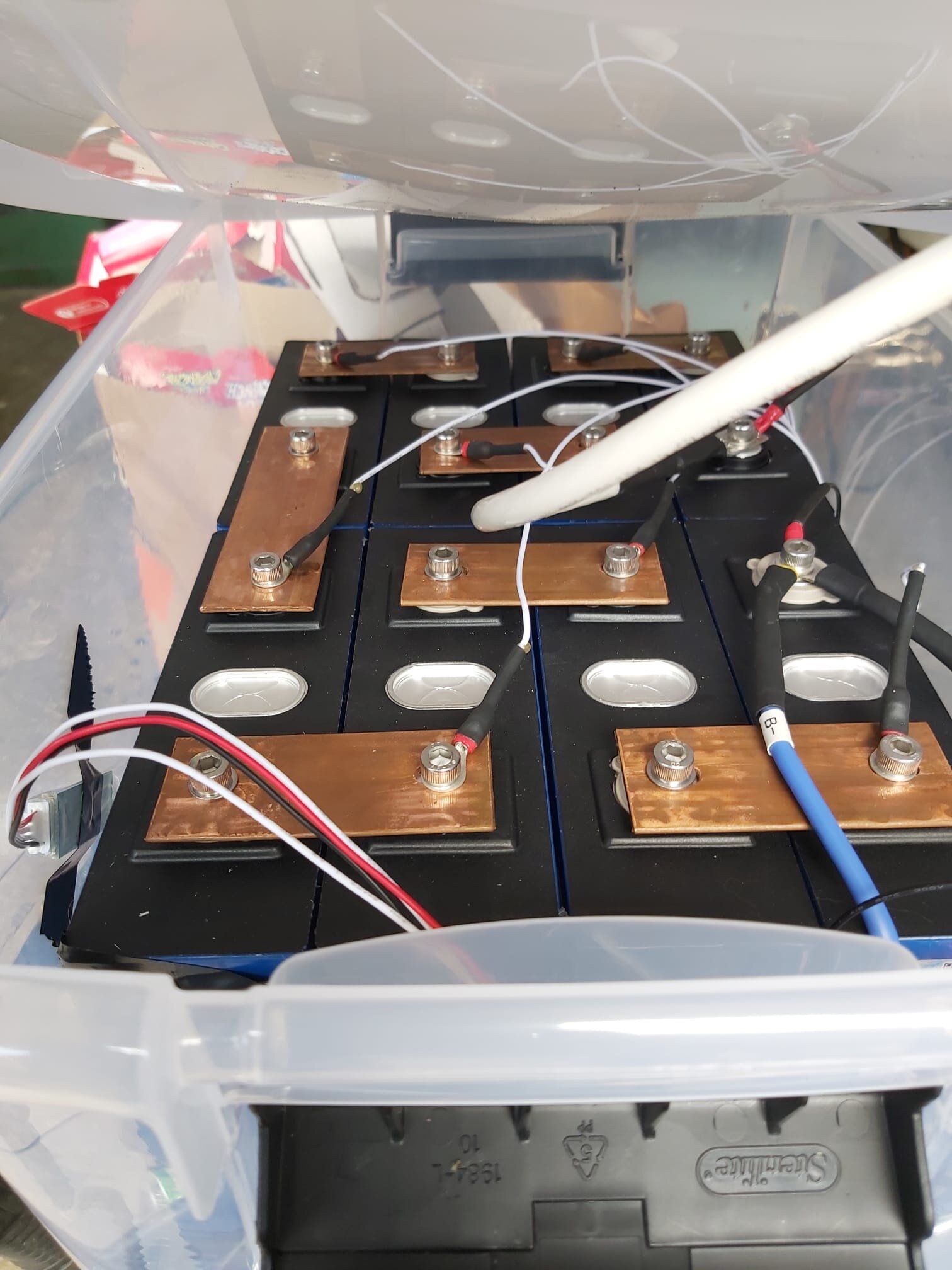
See the Black Wire on the far left of the battery? That is the negative terminal of the battery and the black wire connects to that point. The next wire in the BMS balance lead is a white wire which connects to the same cell groups positive side, which is the other side of that same row of cells. This is the only part of the battery where you will have BMS leads going to both the negative and positive points of the same cell. All the other leads will connect to the positive points of the cell groups.

The next wire on the plug, moving left to right will connect to the next positive point of the battery from left to right.

The reason behind this is simple, the BMS needs to know the voltage of each cell group. To do this, the BMS needs to read the voltage of each cell group, but it uses the most negative as the Negative point in the circuit. If you get the order of the positive wires wrong, you will make the BMS think that one of the cell groups is incredibly high in voltage, as the voltage should increase by 3.xx volts per cell group as they add up in series.

Assuming that each cell is charged to 3.5v, the first positive lead connected to the first row of cells will tell the BMS that their voltage is 3.5, the second will tell the BMS 7.0v and the BMS will calculate that it is 3.5v. If you accidentally connected the second wire to the 3rd group of cells, you would tell the BMS that the “second” group is reading 10.5v, and the BMS would calculate the voltage to be 10.5-3.5= 7.0v in the second string. The BMS shuts down the battery pack if the voltages exceed the safe parameters, which are normally set to have a voltage minimum of 2.5v and a voltage maximum of 3.6v. If you tell the BMS that one of the cells is at 7.0v, it will shut down the whole pack and sadly it might also fry the BMS! Be very careful while you are connecting the balance leads that way the wires don’t get crossed and you don’t fry this expensive piece of equipment.

Once the balance leads are all connected, its just a matter of tiding up the wires so that this spider web of wire can be tamed by the power of zip ties!

After all the leads are tamed, I like to wrap the whole area over with 2 inch wide Kapton tape which holds them all close to the pack and reduces the risk of the wires getting hooked up on something and pulled free.

While the balance leads are the main concern for people who are thinking about building their lithium battery and worry about the BMS, there is one additional component that needs to be connected. The BMS monitors and controls the battery pack by checking its voltage, but it also will shut the pack down if it begins to over heat! Thermal runaway is a huge concern for boaters who are contemplating converting their batteries to Lithium.

The prospect of fitting a huge fire hazard that will continue to burn even underwater is a tough pill to swallow! The BMS has a temperature probe which must be attached (with Kapton tape) to the side of a cell. The BMS will also monitor the temperature of the cell it is attached to and if that cell begins to heat up, it will shut the pack down long before the battery can ignite into an inextinguishable flame.

I like the BMS from Overkill Solar, as it allows you to log into the BMS through a BlueTooth module and set the parameters of the battery manually. I have mine set very conservatively!

Before any parameters get too far out of whack, the BMS shuts down the battery pack and prevents it from getting into dangerous levels.

The BMS also works to balance out the cells in the pack so that if one of the cells is significantly higher voltage, it will balance the voltages and bring it down to safe levels while so that the rest of the cells can continue to charge as a whole.

We have used this BMS for a few months now and motored on the ICW with it powering our electric motor without issue. The solar panels charge up the batteries and this cuts them off when they get full as well as cuts the packs offline when they run empty during long motoring adventures up the ICW.

The best part so far about the lithium batteries for electric propulsion is the fact that you will have full power all the way down to 0% charge when the BMS takes the pack offline. With AGM batteries, the voltage gets low as the charge runs out and the motor just doesn’t have the same oomph that it had when the batteries were fully charged. These lithium batteries let you have full thrust at any state of charge, all the way from 100% down to 0%. The only problem with this wonderful feature is you have to keep an eye on the battery charge level, as you will be motoring along for hours and think everything is fine because the boat isn’t slowing down until the motor just cuts off because the BMS had to disconnect the pack due to one of the cells running out of power. It really is awesome!

If you are contemplating Lithium batteries and considering making them yourself, the BMS shouldn’t be a huge concern. It is just a box with a bunch of wires that need to be connected in a specific order. We managed to make our own batteries in two weeks inside our salon with very simple tools. This saved us thousands of dollars and has afforded us the ability to motor farther and faster on our electric motor.

What is this Gold Tape?

Every time you see fancy electronics, they seem to be covered in a strange golden colored tape. What is it and why should you use it?

The short answer is: It is called Kapton Tape and you should cover all electrical connections with it.

Kapton tape helps to insulate the connections. This prevents accidental short circuits and shocks if something accidentally bumps into the battery! Kapton tape also helps hold everything together, keeping the entire unit sealed up as a neat and clean package.

Kapton tape is also really handy for controlling all the crazy amounts of wires that run around the battery pack for the BMS. A BMS will have one additional wire beyond the number of series connections you are using. For example, if you have a 12v battery, it will have 4 series connections and the BMS will have 5 wires. If you have a 24v battery, you will have 8 series connections and the BMS will have 9 wires. If you build a 48v battery like we did, you will have 16 series connections and the BMS will have 17 wires!

I have found that 2 inch wide tape works great giving you a good amount of coverage while still being easy to manage. The two inch wide tape also fits neatly between the cell holders allowing me to wrap the entire outer edge of the cells in Kapton tape to hold any wires or leads in place, as well as provide an extra protection to the sides of the cells.

Keeping all these wires neatly held together and safely contained inside the battery prevents them from getting snagged on something during transport or when the boat heels over and something shifts position to fall against the battery! Holding everything neatly together inside an electrically insulated pouch helps keep the battery safe for a long service life.

Cell Organization

The list of advantages of cylindrical cells over prismatic cells is pretty small. Cylindrical cells do not rely on the box to provide compression to the cell, they can charge and discharge faster, and they are smaller allowing them to be built to fit custom shaped boxes.

This last point comes in really handy when fitting lithium batteries in your sailboat!

The concept of connecting the cells together is simple. Connect the same ends of the cells together to form your parallel groups, and then connect the parallel group to the opposite charge parallel group.

In other words, hook all the positive cells together in a row making one big patch of positive connections. Then connect all the negative cells together in a row making one big negative patch of connections. Now you have a big positive and a big negative group set up in parallel, when you connect them to each other, they will now be connected in series.

In the top picture, we were making the battery in a square shape, so the positive and negative strings are easy to visualize, as are the series connections linking the positive and negative groups together. This if fine if you are building a square battery because you have plenty of space, and if you have plenty of space, you are probably also considering a preassembled battery which will cost more than the raw components but remove all the effort of building your battery!

When you are building a battery to fit into a strangely shaped box is when the cylindrical cells shine as they allow you to fit them into unique designs.

Think of prismatic cells as a large solid rock! They are their shape and will forever be that shape, regardless of the container that they are placed in. Now think of cylindrical cells as small pebbles. Each one has its shape and will maintain that shape but since they are smaller they can pack in there much more tightly and conform to the container that they are placed in more easily.

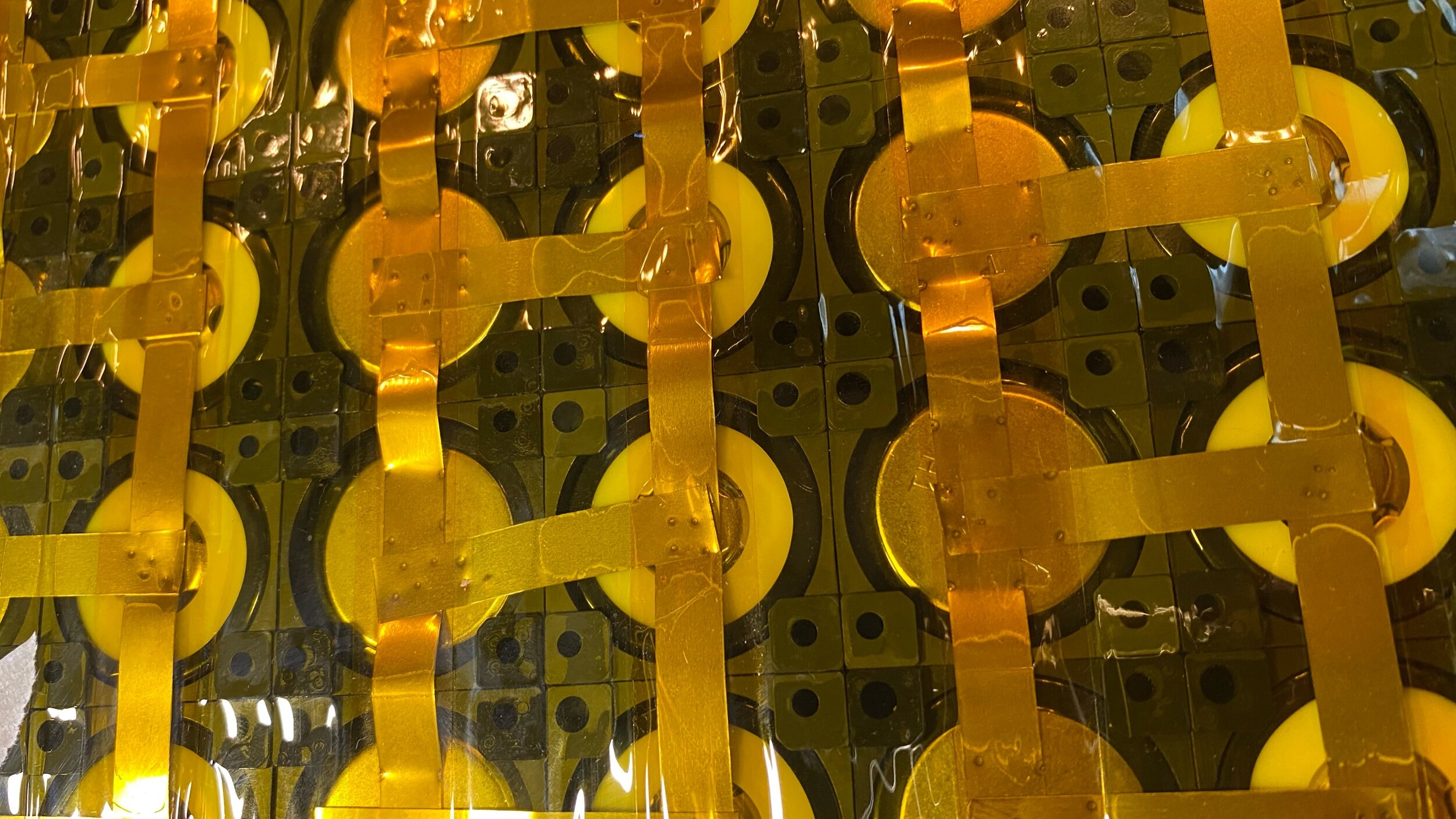
In the square battery, the positive and negative strings are straight; running the entire length of the battery. In the strangely shaped battery, the positive and negative strings are uniquely interlaced as we fit the cells into the space allowed as best we could.

If you look closely, you will see that the square battery where all the positive and negative cells are in a line, there is only one Ni strip connecting between one positive and one negative. On the second image, the battery is not square, but will still be forced to supply the same amount of power, and this means that the same number of interconnects between the positive and negative groups needs to exist.

In the square battery, there were 16 interconnects between the positive and negative. Each interconnect can flow 5 amps giving it the ability to charge and discharge at a rate of 80 amps. The uniquely shaped battery has a bit of an issue, there are far fewer than 16 spots where a positive can connect to the neighboring negative, meaning that the Ni strips will not be able to flow the full 80 amps! To circumvent this caveat, we simply doubled up the Ni strips to bring the total number of interconnects up to 16, allowing the same 80 amps to flow across between the two parallel groups.

If you look closely, you will see some extra Ni strips that bridge the gap and add ampacity to the system, allowing us to use this uniquely shaped battery under the same parameters as the square battery.

Building the battery is only part of the process, you then need to control the battery to avoid any dangerous and explosive events that can occur when a Lithium cell becomes over or under charged. To do this, you will need a BMS or Battery Management System which protects the cells by shutting them down before they get to dangerous levels.

Monitoring and balancing your cells is an important part of Lithium batteries, but not as important as building a safe battery. Imagine if you didn’t take into consideration the ampacity of the Ni strips and ended up building a fuse rather than an interconnect. As the amps start to be drawn from the battery, the interconnects would heat up and that would place a lot of heat right over a Lithium cell. The first thing you should know about Lithium cells is that you can never expose them to heat because they could ignite!

Knowing what you are going to do with your batteries lets you build a battery that will suit those needs and as a result, allow you to build a battery that will safely provide you the power that you need and be safely managed while it provides this power.

Connecting Lithium Cells

Everyone loves math! That’s why everyone designs their own battery packs!!

To make math easier, and build exactly what you need (and not be wasteful by over building your battery), it is important to have the purpose in mind already with the needed parameters for the battery before you even begin assembling parts for said battery.

For example, say you want to build a battery for your boat to run the house loads. This is an excellent application for a lithium battery! Imagine that you turn everything on at the same time in your boat, how many amps will you be drawing?

It is important to remember that your inverter needs to be part of the calculation, and to plan on the inverter running at surge capacity, as this might happen and in that event, the battery needs to be able to manage the load.

For this example, we will think of a boat with a refrigerator, navigation lights, interior lights, and an inverter that runs the boats air conditioner. We will assign powers to these devices and say that the fridge draws 8 amps, the navigation lights draw 0.5 amps, the interior lights draw 5 amps, and the 2000W inverter draws 170 amps (250 amps at surge).

In our example, with everything turned on at the same time, the battery will be asked to provide 183.5 amps (or 263.5 amps during surge). Because electronics are always upgraded as years go by, it’s not a bad idea to factor in some reserves in this battery and call it 300 amps for the plan.

Suddenly, we have a number! 300 amps is what the battery you build needs to be able to supply at a moments notice. With this number, everything becomes a simple matter of arithmetic.

Each cell contains power, but that power can’t go anywhere without a circuit. Inside the battery, these interconnecting pieces are the secret to getting energy from your cells and into your electronics! They are typically metal bars that can flow a certain number of amps. If the bar is not big enough for the current you will asking from it, then it will turn into a fuse and burst into flames as the metal is overheated, until it burns away and breaks the connection; naturally, this is something we want to avoid!

In a previous post, I mentioned the need to decide on cylindrical vs prismatic cells. Cylindrical cells are much smaller while prismatic cells are much larger. This means that each prismatic cell will hold more power while having fewer connections to other cells. Fewer connections also means that each connection suddenly needs to carry more power!

Picture a prismatic 12v battery with a capacity of 100 amps. Each prismatic cell is 3.2v and 100ah. You would be looking at 4 cells, connected in series by 4 plates. This setup would be called a 4s1p battery as it consists of 4 groups in series of 1 group in parallel. This means that each plate will be flowing 100 amps!

Now picture a cylindrical 12v battery with the same capacity of 100 amps. Each cylindrical cell is 3.2v, same as the prismatic, but only hold 5ah. Suddenly, you will have a 20 cells in parallel to make the 100 amps, and 4 groups of them linked up in series to make the 12v battery. This arrangement is called 4s20p as you have 4 groups in series of 20 cells each hooked up in parallel. The interconnects will be a lot more plentiful here but they will still need to flow the full 100 amps.

For cylindrical cells, the common interconnect material is Ni strips. They are 8mm across and 0.15mm thick, and have an ampacity (the amount of amps that they can carry) of 5 amps. To carry the full 100 amps, you will need 20 interconnects running between the parallel groups linking in series to the next group.

This is where the work part comes into the equation, 1 big plate that you bolt on or 20 small strips of metal that need to be spot welded to the ends of the cells. How much is your time worth?

This is great, you built a battery that will be able to supply 100 amps! Excellent, except that your boat needs to be able to draw 300 amps! Either you need to build two more batteries so that each one merely gives up 100 amps at a time as they all work together, or you need to beef up your battery with its interconnects.

In the world of prismatic cells, the metal interconnect bars flow 100amps. All you need to do is place 3 stacked on top of each other so that they can flow 300 amps between the three of them. In the world of cylindrical cells, where the Ni strip flows 5 amps, you suddenly need 60 interconnects instead of just 20!

Things escalate very quickly, but the components are all the same and it’s merely the act of repeating a known process over and over to grant you the result you are looking for. By knowing what you need before you start, you will be able to build the battery that you actually need, instead of guessing and hoping that a random assembly will meet your needs.