Running Rigging

Reefline Setup, a Common Mistake

FullSizeRender.jpg

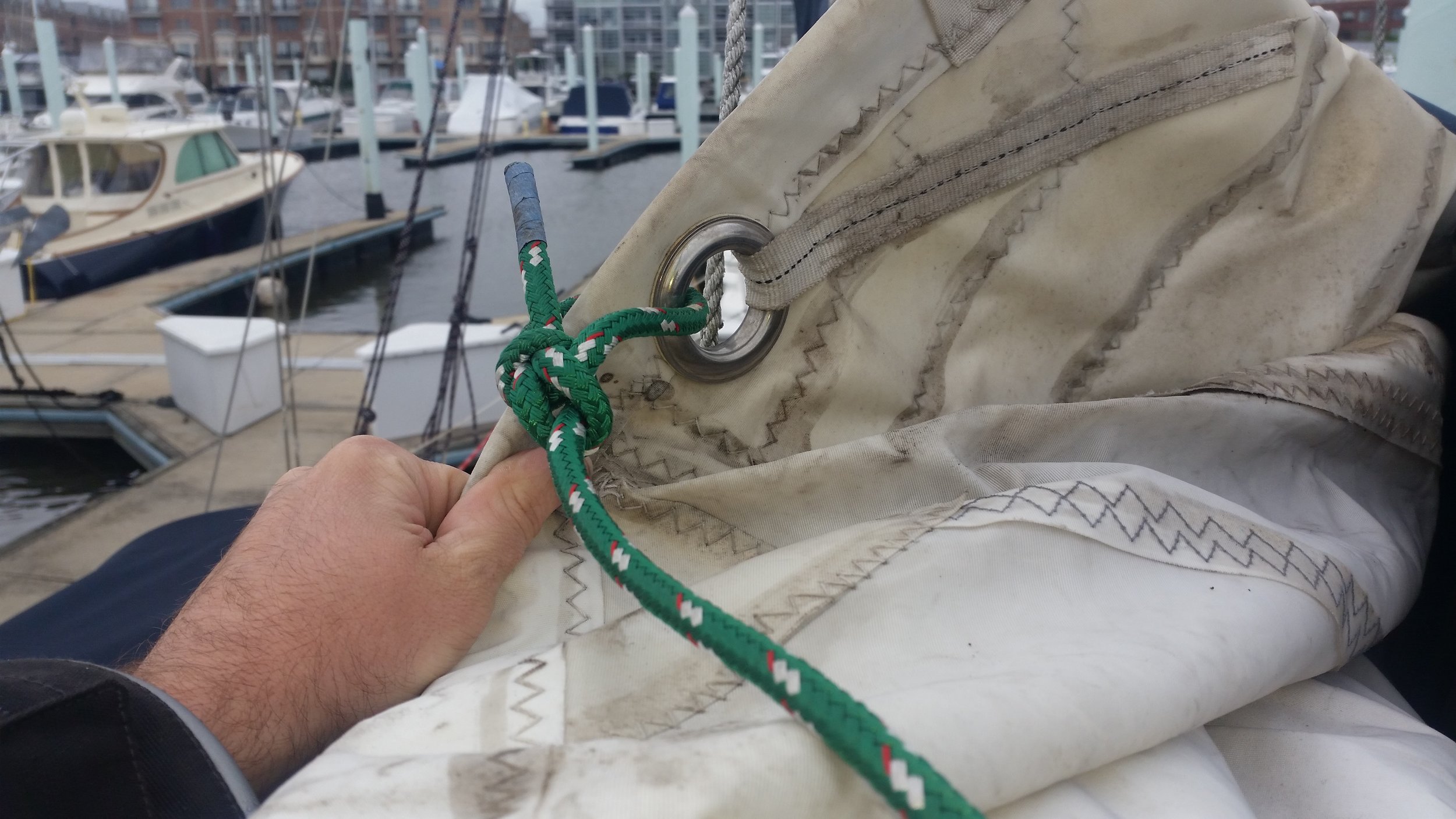
It is very common to see the clew reef line simply tied to the cringle on the leech. This may look fine but it is actually incorrect. 

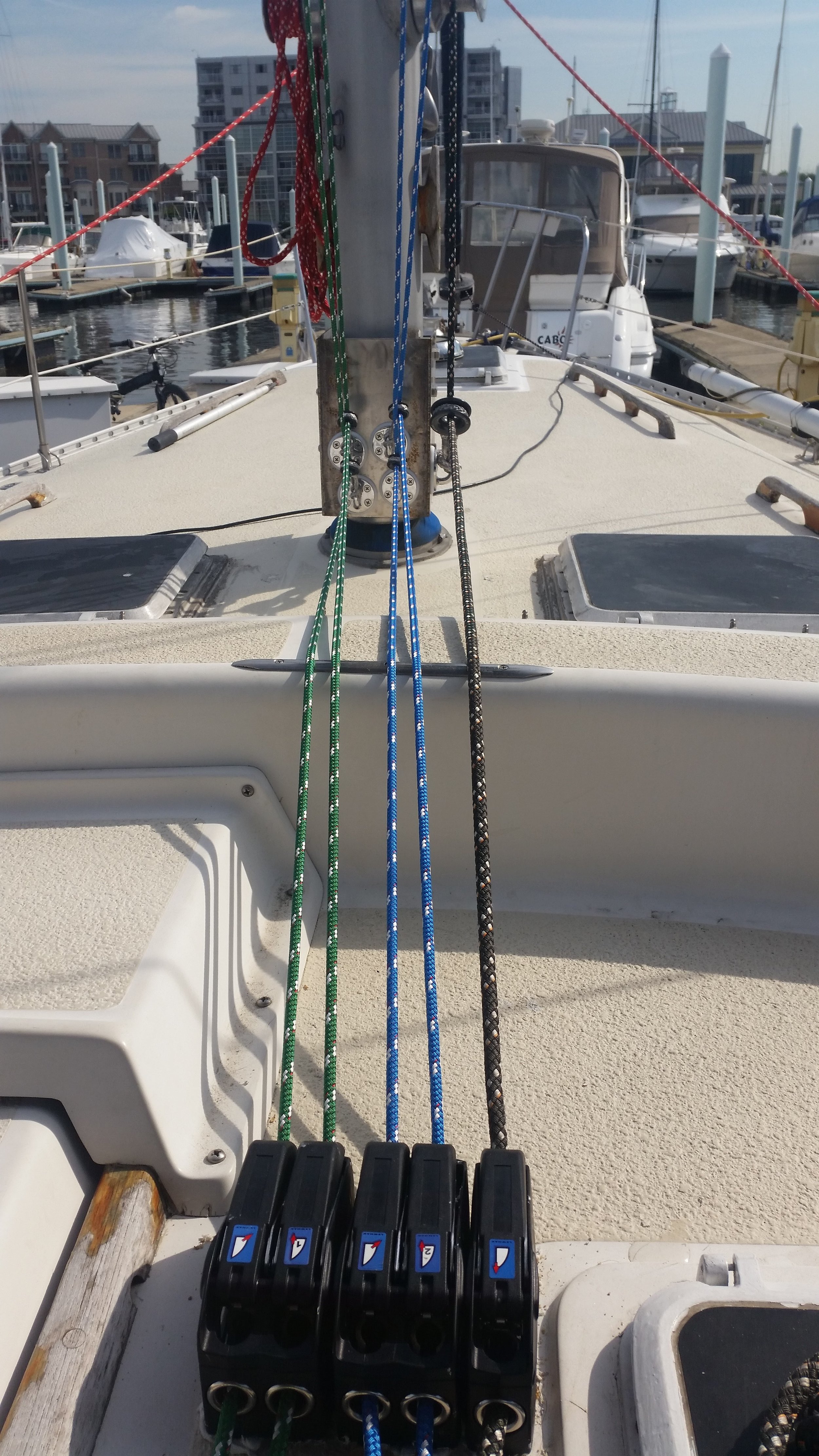
The correct method is to tie the clew line to the boom, lead it up through the cringle, back down to the cheek block, and then forward along the boom.  

You might be thinking, what is the harm, both methods pull the clew cringle back and down. The biggest fault here is the clew line is rather small for the task at hand because it is designed to be passed through the cringle. When you pass it through the cringle, it instantly creates a 2:1 system, where the force on the clew line is evenly distributed between both lines. This means that if you have 1000 pounds of force on the clew line, each section of the line is only subjected to 500 pounds. 

If you simply tie the clew line to the cringle, all the force is put on that line. In our example, that means that the little line now needs to resist the full 1000 pounds when the designers were only calculating its lost at 500 pounds. 

This is a very simple and common mistake, which is why you should inspect your own reef line setup to make sure you don't have a bowline tied to the clew cringle and instead pass it through the cringle and tied to the boom. 

Converting to Lines Led Aft: Part 7, Running the Lines

After all the associated hardware is installed, the last step is to actually run the lines back to the cockpit! This is the moment of truth, where all your planning comes into play and you get to see how it all pans out.  

FullSizeRender.jpg

The lines should be led fair and straight from the mast to the clutch and onto the winch. Each turn and bend adds resistance, so minimizing the number of turns will reduce the effort needed to manage the sail. 

FullSizeRender.jpg

The Antal rings in Dyneema loops allow the block to position itself and move as the sail moves around above it. If the boom swings over to the side, the lines that hold the rings will move as well without question nor effort. The force from these turning blocks is all directed towards the bottom of the bracket, that way all the force is rotational instead of lateral. The four stainless steel bolts are setup to handle this sort of load with ease. 

FullSizeRender.jpg

Lastly, the system needs to work. The lines leaving the clutches need to reach the winch with as little angle as possible. The halyard is going to be under the most load, so it has priority in its placement. The tack and clew lines are set while the sail is slacked, so they can stand to be a little less perfect. I set the first reef to be in the least ideal position since that reef is only taken in when the weather is starting to turn. The second reef is set more ideal since it is taken in when the weather has gone from bad to worse. The halyard has the fairest lead of them all, reaching the winch from a beautiful angle. 

FullSizeRender.jpg

Ignoring the structural and engineering side of it, the last task for this setup is to look sharp. If the lines are running all over the place, it will begin to look haphazard. By keeping everything straight and organized, it just looks good and is easy to understand.  

At a glance, you can see that the green lines work together, and the blue lines belong together as well. The halyard runs off on the side, so it obviously works alone.  This sort of simplicity will allow anyone new to step up to the clutch bank and tuck in a reef when the time is right.

Converting to Lines Led Aft: Part 6, The Holes

Having all of your running rigging led back to the cockpit might sound like a dream come true. Imagine sailing along and the wind pipes up a bit. You reach over and lower the main halyard, crank in on the tack and clew lines and re-tighten the main halyard. All the while, you are standing right next to the helm. That's right, you are able to sheet, reef, raise and lower sail, and steer, all while standing by the helm!

As we learned from fairy tales about genies, all dreams come at a price. In the case of this dream, the price is a slew of holes drilled through your deck! 

FullSizeRender.jpg

The clutches require two holes each and the winch requires another five holes! For a setup like this, we are forced to drill fifteen holes!

FullSizeRender.jpg

Each hole perforated the outer fiberglass skin, core, and inner fiberglass skin. Each hole is also a source of potential leaks that can lead to a rotten core and a soft spot in the deck. For this reason, way too much bedding compound should be used when bedding the bolts and their parts to the deck. Having bedding compound bled out the sides of the clutches and winch base might not look the cleanest, but it does guarantee you that there are no voids under the component. Voids will allow the passage of water and will hold moisture. With time, these voids will be the death of your deck and lead to costly repairs in the future.

Each one of these holes has the potential to cause serious havoc on your yachts structural integrity. The choice to have holes drilled in your deck should be made knowing the potential consequences of the convenience. The counter argument of "Do a good job and make sure that nothing bad will happen" is what we all think while planning and working. The sad thing is, if an invisible flaw occurred, its existence will go unnoticed until catastrophe occurs and rot has set in. Worse than voids while bedding hardware is time. 

Voids lead to obvious problems, time can cause new ones. A perfectly bedded item today may not be so perfect in the future. With time, the bedding compound can loose its elasticity and become brittle. When the component is exposed to a shock load, the bedding compound may snap instead of stretch. This invisible break in the seal will allow the ingress of water and all the failures associated with an improperly bedded item. This is why all hardware is removed and re-bedded during a refit, to address these issues instead of ignoring them. 

All in all, the holes are the shortest part of the job, and also the most stressful part. Each hole will perforate the deck and needs to be sealed up perfectly as if nothing ever happened. Each hole also needs to be lined up with the other holes, allowing the component to be mounted and fastened properly. If any hole is offset, the component will not fit and that hole would have been drilled in vain! 

Converting to Lines Led Aft: Part 5, The Clutch Bank

Lines left on the mast rely on a setup of winches and cleats on the spars where the different lines can be tied. When you convert to lines led aft, you are no longer able to use the setup on your spars for managing the lines and instead must setup a new system where the lines are led to. In this case, the lines are led to the cockpit, so we need to setup a clutch bank and a winch in the comfort of the cockpit that will be able to manage the lines.

FullSizeRender.jpg

Clutches work similarly to cleats, but require no knot tying skill to operate. Instead of needing to tie a cleat hitch in record time while worrying about many other lines, all you need to do is flip a lever and the rope is held in place! Rope clutches work with friction to lock the rope inside its grip when closed, yet allow the rope to pass freely when open. 

Rope clutches also help organize all the lines led to the cockpit. A line will be permanently reeves through the clutch, so you know you can always find it exiting the clutch. This helps minimize the confusion of cockpit spaghetti as the rope will be found in its clutch which will have a label on it to help further identify itself as the line you are looking for. 

Clutches also have another advantage, they allow many lines to share a winch! With a standard setup, the line is led to a which and then tied off to a cleat to secure it in place. This means that the winch will be permanently occupied for as long as that line is in service. This leads to the need for many winches to manage and control all of the lines of the running rigging. Clutches are mounted before the winch and offer the ability to simply lock off the line and remove it from the winch. This in turn allows for another line to be wrapped around the winch, reducing the number of winches needed and the cost associated with multiple winches. 

FullSizeRender.jpg

The last thing you need to focus on before you start drilling holes is where everything will be placed. The clutches need to be in line with the last turning block, which in this case is the bracket on the mast. They also need to be in line with the winch. The angle of deviation between the clutch and winch should be no greater than 15 degrees and no closer than 8 inches. On top of all of these requirements, you also need to find a place that can withstand the structural loads placed upon the new hardware.  

When converting a yacht to a new setup, you need to bear in mind that the yacht was not engineered for this new setup and you need to double check everything to make sure that the structure will be compatible. If it is not, you need to either modify your plans or reinforce the structure to the required specifications. 

I would rather have located the clutch bank farther forward, but that section was hollow with an inner and outer skin. A bit aft, and a strong carlin was running from the companionway to the hatch. This area sounded solid upon percussive examination and was chosen as the desired location for the clutch bank and winch. They may be a bit close together, but they are certainly in sound wood and the loads will be well managed. 

Converting to Lines Led Aft: Part 4, Assembling the Bracket

With the cheek blocks mounted on the boom, it was time to drill the holes and install the padeyes for the mast turning blocks. These blocks will turn the reefing lines and halyard from down to aft, leading the lines back into the cockpit. They will be under a lot of stress and load, which is why they must be incredibly strong.

Bolt holes for the individual padeyes were drilled into the thick stainless steel plate where they would be securely fastened with bolts, nuts, and backing plates to help distribute the loads they will be subjected to.

To add flexibility into the system, we are using Antal Low Friction Rings attached with a dyneema loop. Antal sells pre-made rings in loops for their smaller sizes but not for their larger rings.

I made the dyneema grommet that holds the main halyards ring in the same fashion that I make the dyneema grommets for deadeyes. Instead of inserting thimbles and a seizing knot in the middle, I merely inserted a loop with a seizing knot attached to the padeye with a larks head knot.

With the hardware mounted on the spars and the bracket finished up, the next step will be to install the clutches and the winch in the cockpit.